
Microsolar: a DIY solar energy router
A complete residential micro-solar prototype combining photovoltaic generation, real-time energy measurement, embedded control and a browser-based interface. The system prioritizes self-consumption and redirects surplus power to a water heater instead of exporting it to the grid.
Project overview
Microsolar is a practical engineering project designed to make small balcony or residential photovoltaic systems easier to understand, build and operate. It covers the complete workflow: selecting the electrical components, mounting the panels, assembling the controller, programming the firmware, measuring household power flow and configuring the finished system.
The controller continuously observes the direction and magnitude of grid power. When solar production exceeds immediate household demand, it controls a high-power AC dimmer and transfers the available surplus to a standard electric water heater. This increases local use of generated energy and reduces unwanted feed-in.
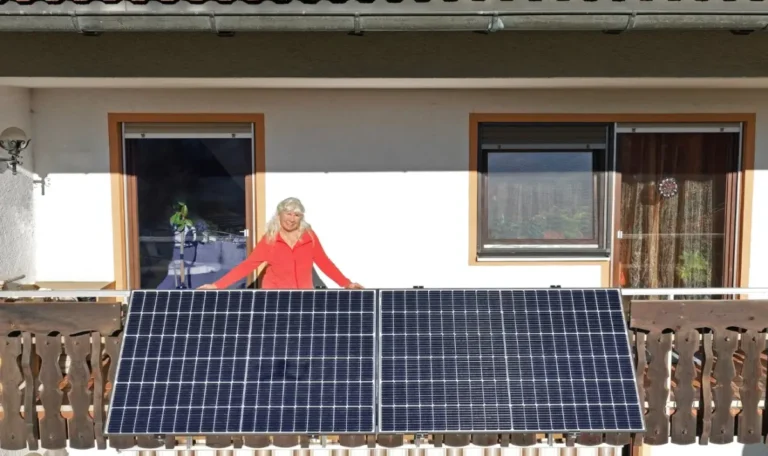
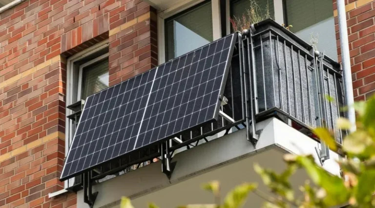
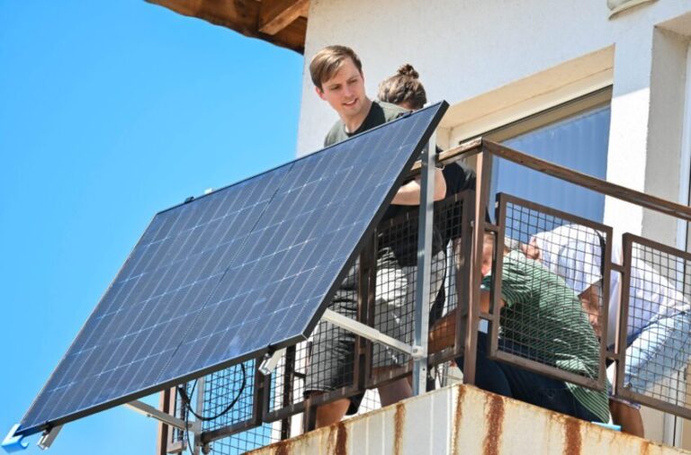
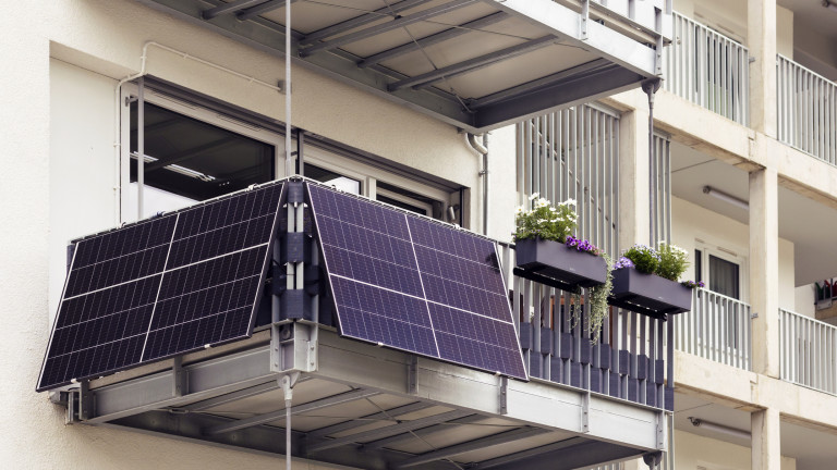
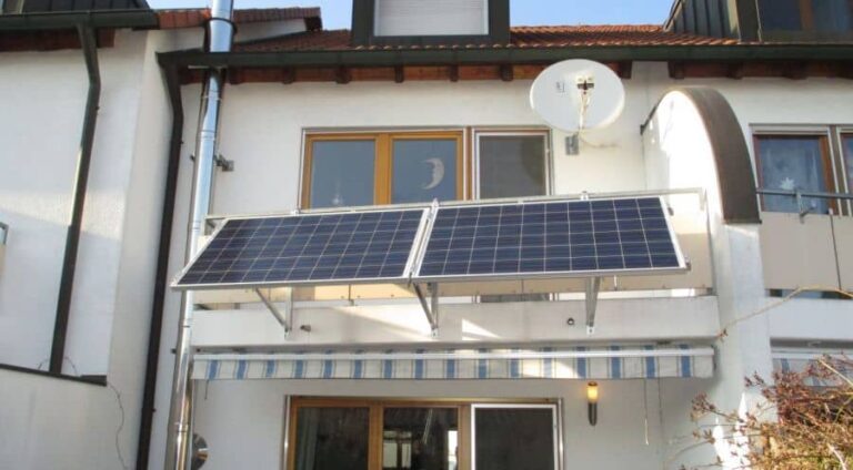
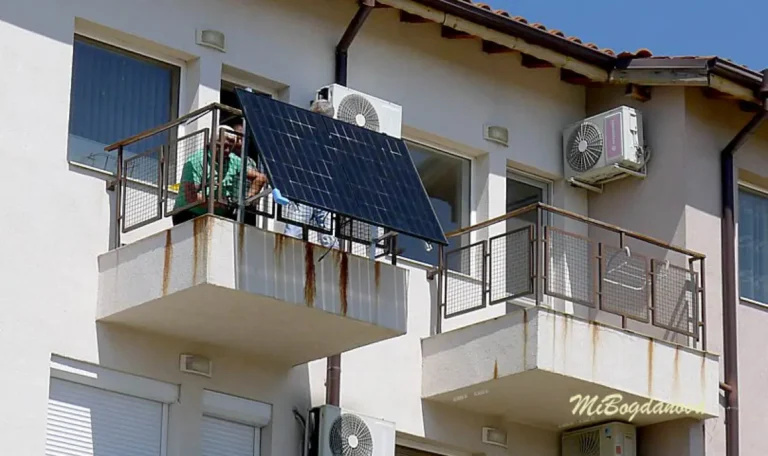
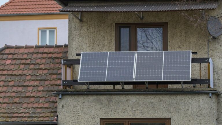
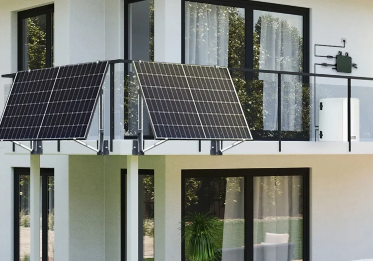
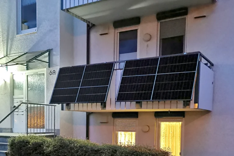
Residential installations
Examples of compact photovoltaic installations on balconies and building façades.

How the system works
Generate
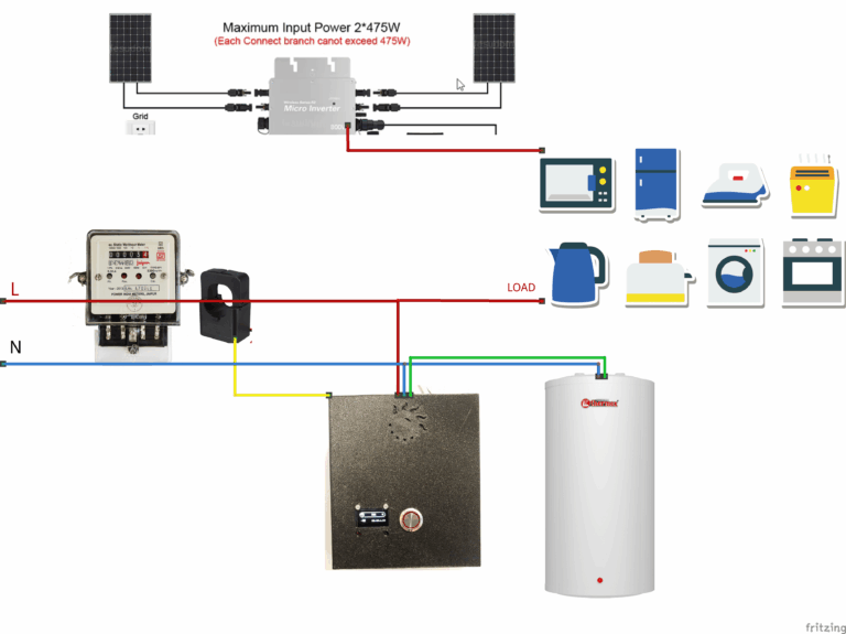
One or more photovoltaic panels feed a grid-tied microinverter.
Measure
A JSY-MK-194T energy sensor measures household import and export in real time.
Decide
ESP32 firmware calculates the available surplus and applies control rules.
Route
An AC dimmer proportionally transfers surplus energy to a water heater.
Engineering implementation
Hardware
- ESP32 development board
- JSY-MK-194T bidirectional energy meter
- 40 A, 600 V AC dimmer with 3.3/5 V logic
- 5 V / 30 A relay and isolated power supply
- I²C OLED status display and local push button
- Grid-tied microinverter and photovoltaic panels
- Custom 3D-printed, flame-retardant PETG enclosure
Firmware and interface
- Embedded C++ firmware developed with Arduino IDE
- Serial communication with the power meter
- Closed-loop surplus-power control
- Manual relay override and scheduled operation
- Local responsive web interface
- Display and time-offset configuration
- Browser-based OTA firmware updates
What I engineered
System integration
Selected and integrated the sensing, processing and power-control components into a functioning end-to-end prototype. Designed the wiring approach, enclosure layout and installation workflow.
Embedded software
Configured the ESP32 toolchain, integrated the measurement sensor, implemented control and scheduling logic, and exposed device functions through a local web interface.
Testing and documentation
Validated the system through staged bench and installation tests, documented component sourcing and assembly, and published downloadable firmware, libraries and enclosure files.
Product thinking
Optimized for affordability, understandable installation and practical household value while keeping the design modular enough for future improvements.
English build guide
This guide summarizes the complete build process for the Microsolar energy router, from component selection and ESP32 setup to enclosure assembly and operation. Read the full guide before starting and adapt the installation to your local electrical code.
0. Safety and scope
- Use correctly rated protective devices, wire sizes, terminals and enclosures.
- Keep low-voltage logic physically separated from mains wiring.
- Use strain relief, insulation, earthing and flame-retardant materials.
- Confirm balcony load capacity, wind loading and panel anchoring.
- Do not energize an incomplete or uncovered assembly.
1. Gather the components
Photovoltaic system
- One or more photovoltaic panels (the prototype uses approximately 450 W panels)
- Grid-tied microinverter matched to the panels and local grid
- 6 mm² solar cable and compatible MC4 connectors
- Solar crimping tool and insulated installation hardware
- Structurally suitable mounting brackets
Energy router
- ESP32 development board
- JSY-MK-194T bidirectional energy meter
- 40 A / 600 V AC dimmer with 3.3 V or 5 V logic
- 5 V / 30 A relay
- I²C OLED display, push button and isolated DC supply
- M3 screws, heat-set inserts and wiring accessories
- Flame-retardant, UL-rated PETG for the enclosure
The original prototype cost was approximately BGN 700. Prices, availability and required certifications vary by country.
2. Configure Arduino IDE and test the ESP32
- Download and install Arduino IDE.
- Open File → Preferences and add this Board Manager URL:
https://raw.githubusercontent.com/espressif/arduino-esp32/gh-pages/package_esp32_index.json - Open Tools → Board → Board Manager, search for esp32 and install the Espressif Systems package. The original build used version 2.0.11; newer versions may require library updates.
- Connect the ESP32 with a data-capable USB cable. Select Tools → Board → NodeMCU-32S and choose the correct COM port.
- Upload the LED test below. A blinking onboard LED confirms that the board, USB driver and toolchain are working.
void setup() {
  pinMode(2, OUTPUT);  // Onboard LED
}

void loop() {
  digitalWrite(2, HIGH);
  delay(500);
  digitalWrite(2, LOW);
  delay(500);
}
3. Configure the JSY-MK-194T energy meter
The prototype changes the meter communication speed from 9600 baud to 38400 baud before loading the final router firmware.
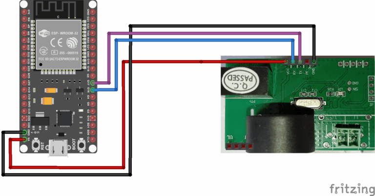
- With the assembly unpowered from mains, connect the meter’s low-voltage communication pins to the ESP32 according to the diagram below.
- Download and upload the baud-rate conversion sketch.
- Run the sketch for several seconds. Power down the low-voltage setup before changing wiring.
- Use 38400 baud in the final firmware configuration.
4. Install the libraries and program the router
- Download the library archive and extract its contents into your Arduino sketchbook libraries directory, normally
C:UsersYourNameDocumentsArduinolibraries. - Download and open Solar_router.ino in Arduino IDE.
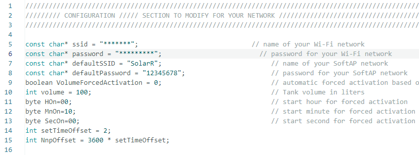
- Set the Wi-Fi SSID and password in the firmware before uploading.
- Set setTimeOffset for your local UTC offset. The original Bulgarian installation uses UTC+3 in summer and UTC+2 in winter; daylight-saving adjustment is manual.
- Compile and upload the firmware to the ESP32.
5. Print and assemble the enclosure
- Download the two enclosure files and print them from flame-retardant, UL-rated PETG or another material approved for the intended environment.
- Install the M3 heat-set inserts and mount the low-voltage electronics securely.
- Maintain clearance, insulation and physical separation between low-voltage and mains-voltage sections.
- Have a qualified electrician complete and verify the mains wiring using the assembly diagram.
- Inspect every terminal, strain relief and protective earth connection before closing the enclosure.
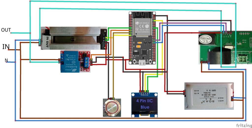

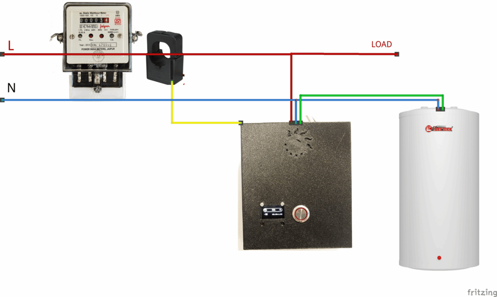
6. Install and commission the system
- Panels: choose mounting hardware for the actual balcony or structure. Two standard panels can add roughly 50 kg of static load before wind and snow loads are considered. Obtain structural approval where required.
- Microinverter: mount it in a ventilated location protected from direct sun and rain, following the manufacturer’s instructions.
- Router: mount the closed enclosure securely, with the display at a readable height and suitable access for service.
- Current transformer: the clamp orientation determines the sign of measured power. In the original installation, its arrow points toward the grid input. Verify direction from live readings during commissioning.
- Functional test: start with low available solar power, confirm measurement polarity, then verify that routed power increases smoothly without exporting energy.
Do not commission the mains side alone unless you are qualified and legally permitted to perform this work.
7. Use the local web interface
After startup, the OLED displays the IP address assigned by your Wi-Fi router. Enter that address in a browser on the same local network.
- Force Mode: manually activates the relay for testing or override.
- Clock On/Off: enables scheduled operation, for example during a lower-cost electricity tariff.
- Screen On/Off: controls the OLED display.
- Time settings: configure the scheduled start time and UTC offset.
- OTA update: open
http://<device-ip>/updateto upload a newly compiled.binfirmware file.
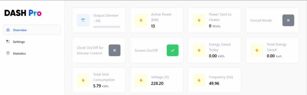
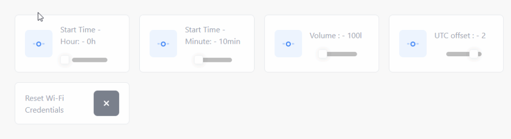
8. Final checks
- Enclosure closed, secure and correctly labelled
- All mains work inspected and tested by a qualified electrician
- Measurement direction and power values verified
- Web interface reachable from the local network
- Relay, schedule, display and OTA page tested
- Surplus routing verified under gradually increasing solar production
Once these checks pass, monitor the system closely during its first operating days and periodically inspect terminals, temperature and mounting hardware.
Project resources
Explore the original Bulgarian build guide or download selected project files.
Performance and cost figures are approximate and depend on the installation, solar exposure, component pricing and household consumption profile.